This application uses the SMS or text messaging service of the mobile phone network to monitor inputs and control outputs. In this version only the digital inputs are monitored.
Outgoing messages triggered from input changes can be sent to a single telephone. Incoming messages can be from any telephone and can be password protected.
Outgoing messages are generated when an input changes state. Which inputs are used and whether they generate the message from an active transition or inactive transition can be defined using the interface application.
Only a single outgoing message can be defined but that can contain dynamic variables which can report on the input and output status as well as which input triggered the message.
Dynamic variables can have a number of additional arguments which can be used to customize the page. For example in its simplest form an input may report with a 1 for on and 0 for off. However by adding extra arguments the input may report with say Alarm and Clear or On and Off.
Incoming messages can be used to control outputs in a variety of ways. Outputs can be set to active, inactive, toggled or pulsed. Each action can be described with its own custom message. Any number of outputs can be controlled in a single message in any combination of actions.
In addition to controlling outputs a status message can be requested and again this can be part of a control message. Thus it is possible to switch an output and get a confirmation message in response.
An input can be defined which when active will inhibit the sending of messages. This could be controlled from an output from external equipment such as a security control panel or it can be wired to one of the EMACSYS outputs so that the reporting may be turned on and from a message.
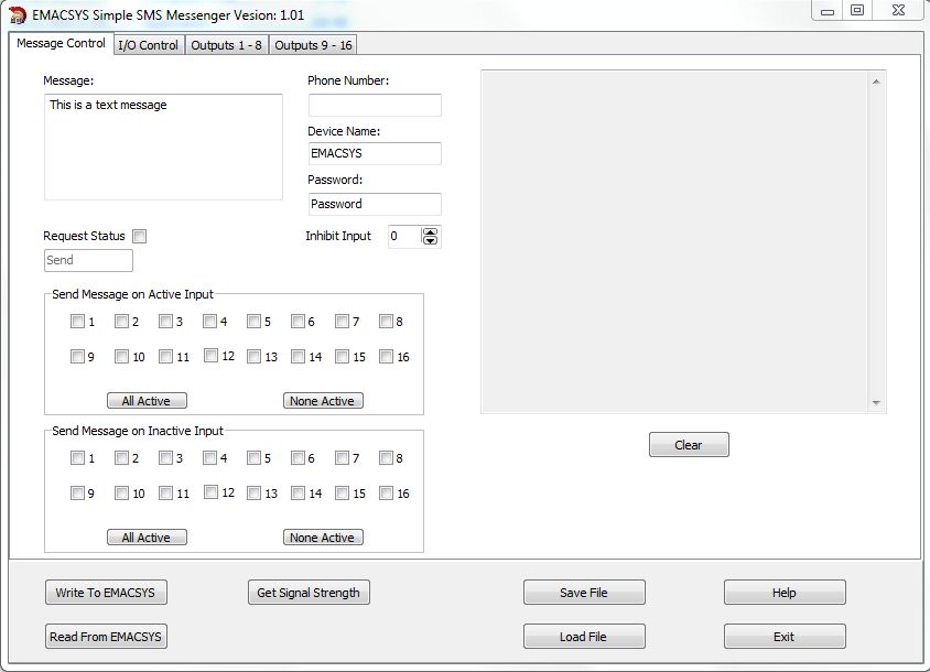
Screen shot of the message control page of the interface application. At the top left is the message definition area. Messages can contain dynamic content which will be substituted with current data when the message is sent. To the right of that is the destination telephone number, device name and password.
Below is the request status definition and the input control area.
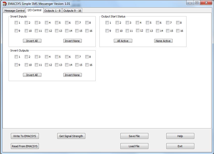
Input and output control page. Here you set the active and inactive polarity and the start status of the outputs.
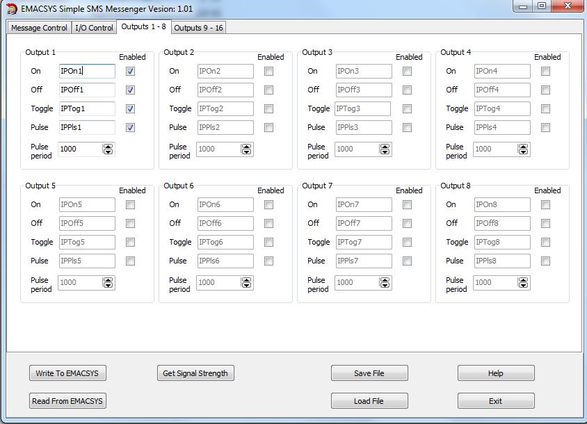
This page defines the messages use to control the outputs from an incoming message. Each output can be set active or inactive, toggled or pulsed.
At the bottom of the page there are buttons for loading and saving the data and for loading and reading from EMACSYS via the USB port.
There is also a facility to monitor the signal strength of the modem again via the USB port.
It is possible to measure the signal strength of the modem via the USB port. This can be a great help to site the aerial for the best signal level.
Hardware requirements:
EMACSYS control module.
EMACSY GSM / GPRS Modem Module
I/O as required.